Reversing a tricky ELF.
This is a writeup for the Tiny Crackme challenge made by Redford, which was part of ECSC 2025 during the first competition day, that I played together with Team Hungary.
The challenge is in the rev category, and it is a small file, so should be seemingly easy to solve.
Initial analysis
I downloaded the challenge binary and saw it's statically linked, stripped and less than 3KB.
Loading it into ghidra, I saw that there's no main function, instead the main application logic directly appears at the entry point of the ELF file.
The actual decompilation is not that nice, since ghidra doesn't recognize that the final syscall is exit and execution should never go past that point.
void processEntry entry(undefined8 param_1,long param_2,char *param_3,char *param_4)

{
  byte *pbVar1;
  long lVar2;
  char *in_RCX;
  long unaff_retaddr;
  bool bVar3;

                    /* argc */
  if (param_2 == 2) {
    lVar2 = chk_flag(param_4);
    strlen(-lVar2 & 0x1046c1U | ~-lVar2 & 0x1046d9U);
    syscall();
    syscall();
                    /* WARNING: Bad instruction - Truncating control flow here */
    halt_baddata();
  }
                    /* usage */
  syscall();
  bVar3 = false;
  if (param_2 == 0) {
    param_3 = "tiny-crackme";
  }
  strlen(param_3,param_3,7);
  syscall();
  syscall();
  syscall();
  // ...
}
Although I already renamed some functions, the logic is quite easy to see, especially when looking at it in just a debugger.
The binary gets the flag as the first argument to the binary, and then runs a checker function. Based on the result we either get that the input is correct or incorrect printed to stdout.
Looking at the chk_flag function we see the following:
undefined8 chk_flag(char *param_1)

{
  long *plVar1;
  undefined8 uVar2;
  long *plVar3;
  long *plVar4;
  long *plVar5;
  ulong idx;
  long local_c98 [4];
  long local_c78 [396];
  ulong flag_len;
  char *flag;

  flag = param_1;
  flag_len = strlen();
  if ((flag_len == 0) || (100 < flag_len)) {
    uVar2 = 0;
  }
  else {
    idx = 0;
    plVar1 = local_c98;
    plVar3 = local_c78;
    plVar4 = (long *)0;
    do {
      plVar5 = plVar1;
      *plVar5 = (long)plVar4;
      plVar5[1] = 0;
      plVar5[2] = (long)plVar3;
      *(short *)(plVar5 + 3) = (short)flag_len;
      *(short *)(plVar5 + 3) = *(short *)(plVar5 + 3) - (short)idx;
      *(ushort *)((long)plVar5 + 0x1a) = (ushort)(byte)flag[idx];
      idx = idx + 1;
      plVar1 = plVar3;
      plVar3 = plVar3 + 4;
      plVar4 = plVar5;
    } while (idx < flag_len);
    plVar5[2] = 0;
    idx = 0;
                    /* sum input */
    while (idx = idx + 1, idx < flag_len) {
      *(short *)((long)plVar5 + -6) =
           *(short *)((long)plVar5 + -6) + *(short *)((long)plVar5 + 0x1a);
      plVar5 = plVar5 + -4;
    }
    uVar2 = actual_check(&DAT_00104790,0x362,local_c98);
  }
  return uVar2;
}
- We see the flag should be less than 100 chars.
- We see that the first loop is setting up some kind of structure, and at offset
0x1athe flag byte is stored. - We see that the second loop is going over each structure in the array and sums up the flag bytes in reverse order.
Then we are ready to do the actual_check, this first function was just the input preprocessing part.
The arguments are some pointer to hardcoded bytes, a constant integer value and the pointer to the start of the structure we have just constructed.
Here's the start of the function, without renaming or adding any types:
  local_10 = param_1;
  local_18 = param_2;
  local_20 = param_3;
  plVar13 = (long *)(param_2 + (long)param_1);
  pplVar10 = local_460;
  local_468 = local_460;
  while (pplVar9 = local_20, param_1 < plVar13) {
    cVar2 = *(char *)param_1;
    if (cVar2 == '\0') {
      bVar3 = *(byte *)((long)param_1 + 1);
      *(undefined2 *)(aplStack_60 + bVar3) = *(undefined2 *)((long)param_1 + 2);
      param_1 = (long *)((long)param_1 + 4);
      pplVar10 = aplStack_60 + bVar3;
    }
    else if (cVar2 == '\x01') {
      bVar3 = *(byte *)((long)param_1 + 1);
      *(undefined2 *)(aplStack_60 + (long)(long **)(ulong)bVar3) =
           *(undefined2 *)(aplStack_60 + *(byte *)((long)param_1 + 2));
      param_1 = (long *)((long)param_1 + 3);
      pplVar10 = (long **)(ulong)bVar3;
    }
This structure should be quite familiar to reverse players, we have a loop which loads a byte from the hardcoded bytes (param_1 is the pointer, from which we store the first byte in cVar2).
Then we compare this first byte to several values (here 0 and 1, the rest omitted for clarity).
This is a VM challenge!
If I do a bit of renaming and mess around with types, the first 2 operations become quite clear:
    if (cVar2 == '\0') {
      bVar3 = *(byte *)((long)pc + 1);
      *(undefined2 *)(reg_base + bVar3) = *(undefined2 *)((long)pc + 2);
      pc = (long *)((long)pc + 4);
      tmp = (long **)(reg_base + bVar3);
    }
    else if (cVar2 == '\x01') {
      bVar3 = *(byte *)((long)pc + 1);
      *(undefined2 *)(reg_base + (long)(long **)(ulong)bVar3) =
           *(undefined2 *)(reg_base + *(byte *)((long)pc + 2));
      pc = (long *)((long)pc + 3);
      tmp = (long **)(ulong)bVar3;
    }
Opcode 0 will load a value from the bytecode to a register (so mov immediate). Opcode 1 will take the value of a register and assign it to the other (so mov register).
With this in mind, we simply need to understand what the VM does and then see how that can help us recover the flag. To that end I wrote a quick disassembler, that given the bytes dumped from the binary can disassemble the VM instructions.
from pwn import *
import content
bc = content.data

ptr = 0
# ptr = 756

while ptr < len(bc):
    opc = bc[ptr]
    print(ptr, end=': ')
    if opc == 0x00:
        reg = bc[ptr+1]
        val = u16(bc[ptr+2:ptr+4], signed=True)
        print(f'mov r{reg}, {val}')
        ptr += 4
    elif opc == 0x01:
        reg1 = bc[ptr+1]
        reg2 = bc[ptr+2]
        print(f'mov r{reg1}, r{reg2}')
        ptr += 3
    elif opc == 0x02:
        reg = bc[ptr+1]
        val = bc[ptr+2]
        print(f'shl r{reg}, {val}')
        ptr += 3
    elif opc == 0x03:
        reg = bc[ptr+1]
        val = bc[ptr+2]
        print(f'shr r{reg}, {val}')
        ptr += 3
    elif opc == 0x04:
        reg = bc[ptr+1]
        val = bc[ptr+2]
        print(f'and r{reg}, r{val}')
        ptr += 3
    elif opc == 0x05:
        reg = bc[ptr+1]
        val = bc[ptr+2]
        print(f'add r{reg}, r{val}')
        ptr += 3
    elif opc == 0x06:
        reg = bc[ptr+1]
        val = bc[ptr+2]
        print(f'sub r{reg}, r{val}')
        ptr += 3
    elif opc == 0x07:
        reg = bc[ptr+1]
        val = bc[ptr+2]
        print(f'or r{reg}, r{val}')
        ptr += 3
    elif opc == 0x08:
        reg = bc[ptr+1]
        val = bc[ptr+2]
        print(f'xor r{reg}, r{val}')
        ptr += 3
    elif opc == 0x0a:
        call_loc = u16(bc[ptr+1:ptr+3])
        print(f'call {call_loc}')
        ptr += 3
    elif opc == 0x0b:
        print('ret')
        ptr += 1
    elif opc == 0x0c:
        jmp_loc = u16(bc[ptr+1:ptr+3])
        print(f'jmp {jmp_loc}')
        ptr += 3
    elif opc == 0x0d:
        reg = bc[ptr+1]
        jmp_loc = u16(bc[ptr+2:ptr+4])
        print(f'jz r{reg} => {jmp_loc}')
        ptr += 4
    elif opc == 0x0e:
        reg = bc[ptr+1]
        jmp_loc = u16(bc[ptr+2:ptr+4])
        print(f'jnz r{reg} => {jmp_loc}')
        ptr += 4
    elif opc == 0x0f:
        reg = bc[ptr+1]
        print(f'exit r{reg}')
        ptr += 2
    elif opc == 0x14:
        reg = bc[ptr+1]
        print(f'mov r{reg}, word ptr [inp+0x18]')
        ptr += 2
    elif opc == 0x15:
        reg = bc[ptr+1]
        print(f'mov r{reg}, word ptr [inp+0x1a]')
        ptr += 2
    elif opc == 0x16:
        print(f'inp = qword ptr [inp + 0x08]')
        ptr += 1
    elif opc == 0x17:
        print(f'inp = qword ptr [inp + 0x10]')
        ptr += 1
    elif opc == 0x18:
        print(f'inp = qword ptr [inp + 0x00]')
        ptr += 1
    elif opc == 0x19:
        print(f'WTF.opcode')
        ptr += 1
    else:
        print('invalid opcode', ptr, bc[ptr])
        break
We'll come to WTF.opcode a bit later :)
For clarity I will not post the full disassembly here, but let's examine certain interesting parts of it!
0: call 756
3: mov r0, word ptr [inp+0x18]
5: mov r3, 40
9: xor r0, r3
12: jnz r0 => 751
16: mov r2, 0
20: mov r7, 1
24: mov r0, word ptr [inp+0x1a]
26: mov r1, 3574
30: sub r0, r1
33: jnz r0 => 40
37: add r2, r7
40: inp = qword ptr [inp + 0x08]
41: mov r0, word ptr [inp+0x1a]
43: mov r1, 2223
47: sub r0, r1
50: jnz r0 => 57
54: add r2, r7
57: inp = qword ptr [inp + 0x08]
58: mov r0, word ptr [inp+0x1a]
60: mov r1, 1405
64: sub r0, r1
67: jnz r0 => 74
71: add r2, r7
This is the start of the bytecode (as you can tell by the offset on the left hand side of the :).
Ignoring the call at the start for a bit, first the length of the input is checked to be 40, then we see a clear pattern of comparisons.
- Setup
r7to be 1 andr2to be 0.r7will just hold constant 1, whiler2will be the return value the VM exits with towards the end of this function. By analysing the code earlier we can discover that we want a non-zero exit code in order to get the success message. - Move flag byte prefix sum from
inp+0x1aintor0(recall at offset0x1awe have the prefix sum of the user input in reverse order). - Move a fixed constant value into
r1,3574for the first time. - Subtract
r1fromr0 - If the result is not zero (i.e the prefix sum is not equal to the constant value), then we jump over the next instruction, which just adds
r7(which is 1) tor2.
Then you can see this cycle repeat, but with one important change, inp is changed to qword ptr [inp+0x08].
Looking at more of the disassembly, this pattern follows, but sometimes the change is to inp+0x10 or inp+0x00.
inp is the pointer to the struct that got constructed in the chk_flag function at the start.
Understanding the structure
Instead of trying too hard to figure out based on the decompiled code, we also have the option to just inspect it in the debugger!
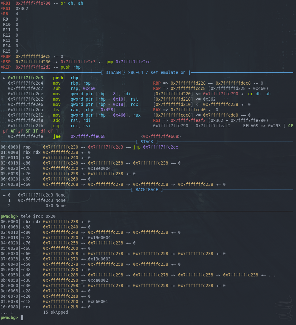
Here I entered asdf as my input to the binary and you can see the reverse prefix sum nicely.
The last item is 0x66 or f in ASCII, then 0xca, which is 0x66 + 0x64, and 0x64 is for letter d.
What is more important is that you can see the pointers of each member of the array. One member has a size of 32 bytes.
For the first member the first 2 pointers are 0, and the last pointer points to the start of the next member.
For the second member the first pointer points to the first member, the second pointer is empty and the 3rd pointer points to the second (i.e next) member.
Looking at the last member, we see the first pointer points to the previous member and the 2nd and 3rd pointers are null.
This is a Linked List! The pointer at offset 0x00 is the previous pointer, while the pointer at offset +0x10 is the next pointer.
We also have 2 integers at offset 0x18, the first is the 1-based index, the second is the reverse prefix sum of the input bytes.
This is all fine, until we recall that the disassembly visits the pointer at offset 0x08, which is always zero for our example. Even having a 40 character input will not populate the middle pointer with anything non-null.
This would surely mean that the VM crashes upon null dereference, but we don't observe such a behavior.
But recall that we have a few unknowns left to discover (and then some more), such as the first function call in the VM, or the WTF.opcode.
Actually understanding the structure
Our previous analysis is correct, but some other transformation is done on the linked list, before the rest of the VM code can actually check it.
Let's look at the function call at offset 756 in the bytecode:
756: mov r0, word ptr [inp+0x18] ; idx of cur element
758: mov r7, 1
762: add r0, r7 ; idx + 1
765: mov r1, r0 ; idx + 1
768: mov r2, r0 ; idx + 1
771: sub r2, r7 ; idx
774: and r0, r2 ; (idx + 1) & idx
777: jnz r0 => 765
781: sub r1, r7
784: mov r6, r1
787: mov r0, word ptr [inp+0x18]
789: sub r0, r6
792: call 825
795: mov r5, r6
798: jz r5 => 824
802: sub r5, r7
805: jz r5 => 824
809: add r5, r7
812: shr r5, 1
815: mov r0, r5
818: call 825
821: jmp 798
824: ret
It seems to do something with the index, of the current element there's some bitwise and, there's some loop and there's also a call to 825.
Let's see is 825 gives us a clue about what is happening here:
825: jz r0 => 865
829: mov r1, r0
832: jz r1 => 848
836: sub r1, r7
839: WTF.opcode
840: jz r1 => 845
844: inp = qword ptr [inp + 0x10] ; next pointer
845: jmp 832
848: mov r1, r0
851: sub r1, r7
854: jz r1 => 865
858: sub r1, r7
861: inp = qword ptr [inp + 0x00] ; prev pointer
862: jmp 854
865: ret
Oh no, it uses WTF.opcode, an opcode I did not bother to understand at first, as it was much longer and with a lot of pointer magic compared to the others.
We also see it moves the inp pointer to the next and previous ones in some sort of loop.
The disassembly is not super clear about what should be happening here, but maybe the opcode implementation is still helpful to look at?
    pplVar6 = (long **)local_20[2];
    plVar7 = *local_20;
    *local_20 = (long *)pplVar6;
    *pplVar6 = plVar7;
    if (plVar7 != (long *)0x0) {
      if ((((long **)plVar7[1] == local_20) &&
          (plVar7[1] = (long)pplVar6, (long **)plVar7[2] == local_20)) ||
         ((long **)plVar7[2] != local_20)) break;
      plVar7[2] = (long)pplVar6;
    }
    tmp = (long **)pplVar6[1];
    local_20[2] = (long *)tmp;
    if (tmp != (long **)0x0) {
      *tmp = (long *)local_20;
    }
    pplVar6[1] = (long *)local_20;
    sVar5 = *(short *)(pplVar6 + 3);
    *(undefined2 *)(pplVar6 + 3) = *(undefined2 *)(local_20 + 3);
    *(short *)(local_20 + 3) = *(short *)(local_20 + 3) - sVar5;
    if (local_20[2] != (long *)0x0) {
      *(short *)(local_20 + 3) = *(short *)(local_20 + 3) + *(short *)(local_20[2] + 3);
    }
    sVar5 = *(short *)((long)pplVar6 + 0x1a);
    *(undefined2 *)((long)pplVar6 + 0x1a) = *(undefined2 *)((long)local_20 + 0x1a);
    *(short *)((long)local_20 + 0x1a) = *(short *)((long)local_20 + 0x1a) - sVar5;
    if (local_20[2] != (long *)0x0) {
      *(short *)((long)local_20 + 0x1a) =
           *(short *)((long)local_20 + 0x1a) + *(short *)((long)local_20[2] + 0x1a);
    }
    pc = (long *)((long)pc + 1);
    tmp = local_20;
    local_20 = pplVar6;
well yeah, this is not super helpful in its current form, but even after renaming and adding a custom struct to ghidra it's not quite clear:
    p_next = inp_ptr->next;
    p_tmp = inp_ptr->prev;
    inp_ptr->prev = p_next;
    p_next->prev = p_tmp;
    if (p_tmp != (ll *)0x0) {
      if (((p_tmp->idk == inp_ptr) && (p_tmp->idk = p_next, p_tmp->next == inp_ptr)) ||
         (p_tmp->next != inp_ptr)) break;
      p_tmp->next = p_next;
    }
    p_tmp = p_next->idk;
    inp_ptr->next = p_tmp;
    if (p_tmp != (ll *)0x0) {
      p_tmp->prev = inp_ptr;
    }
    p_next->idk = inp_ptr;
    sVar4 = p_next->idx;
    p_next->idx = inp_ptr->idx;
    inp_ptr->idx = inp_ptr->idx - sVar4;
    if (inp_ptr->next != (ll *)0x0) {
      inp_ptr->idx = inp_ptr->idx + inp_ptr->next->idx;
    }
    sVar4 = p_next->sum;
    p_next->sum = inp_ptr->sum;
    inp_ptr->sum = inp_ptr->sum - sVar4;
    if (inp_ptr->next != (ll *)0x0) {
      inp_ptr->sum = inp_ptr->sum + inp_ptr->next->sum;
    }
    inp_ptr = p_next;
    pc = (byte *)(pc + 1);
    p_next = plVar6;
at the bottom we can see if we have a next element, then both the index and the sum of the current element is increased by it.
idk is the middle pointer that we don't know the purpose of just yet, but we at least know it gets assigned based on the next and prev pointers of the current element, and then the elements pointed to by these.
Because this again looks to be quite messy let's try instead with dynamic analysis again.
This time, let's try with 8 characters (ABCDEFGH) in the user input, such that we have a better chance of establishing a pattern if there is one.
To be able to inspect the structure, we would like to break after a VM instruction, specifically after the call. We already know the offset of this instruction from the start of the bytecode is 3, so we can set a conditional breakpoint in GDB on the instruction fetch of the VM, with the condition of the program counter being offset 3 from the base of the bytecode.
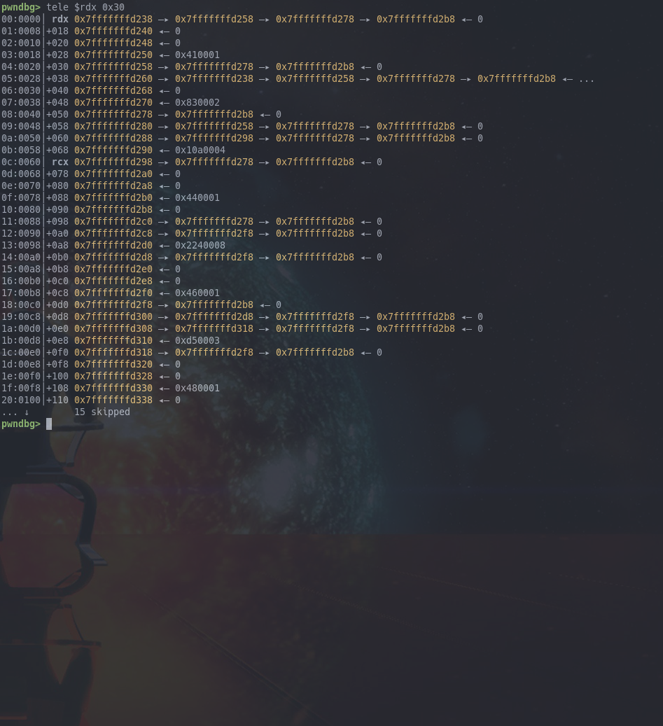
As you can see now some members of the array have the second idk pointer set.
To gain a better understanding of this, it's useful to draw the connection between the different array elements.
A node will be marked by the offset of the array element (lower 12 bits only for clarity), and we will draw edges to all other nodes that are pointed to by the current node. Additionally next to the node we will also note the corresponding value of the array element, and also the index value.

As you can see the structure ends up being a binary tree. Furthermore, note how all leaf nodes of the tree are flag bytes, and all other inner nodes are the sum of their children, plus some remaining value.
For example, on the left: node 258 has value 0x83, and if we subtract its only child node 238 with value 0x41, we have 0x42 remaining, another character in the user input.
So subtracting the sum of the child node values from the parent nodes we recover all of the user input bytes. Furthermore, notice that the order of these characters is just the pre-order traversal of the binary tree.
So now that we know what the structure is and we understand the values of the nodes of the tree, we can begin creating a recovery algorithm.
Recovering the flag
The first task is to parse the disassembly to retrieve the tree traversals and the constant values that the nodes are supposed to have.
The following python script will do just that:
content = open('./dis.txt', 'r').read().split('\n')[5:-49]

ptr = 0
tokens = ''
while ptr < len(content):
    cont = content[ptr]
    if 'inp + 0x00' in cont:
        tokens += 'U'
    elif 'inp + 0x08' in cont:
        tokens += 'L'
    elif 'inp + 0x10' in cont:
        tokens += 'R'
    elif 'mov r1' in cont:
        tokens += f';{cont.split(", ")[1]};'

    ptr += 1

print('toks', tokens)
This will generate some tokens, each node value separated by ; followed by some moves (optionally just one move) on the tree.
Uwill go to the parent of the current nodeRwill go to the right child of the current nodeLwill go to the left child of the current node
Now that we have a more friendly format for the tree traversal it's time to actually reconstruct the tree in python:
from pwn import *
toks = '3574;L;2223;L;1405;L;639;L;349;L;121;UR;117;UUR;251;L;118;UR;32;UUUR;668;L;312;L;101;UR;110;UUR;324;L;102;UR;111;UUUUR;710;L;277;L;201;L;101;UUR;32;UUR;317;L;104;UR;116;UUUUR;1312;L;632;L;257;L;115;UR;110;UUR;264;L;116;UR;116;UUUR;576;L;235;L;101;UR;102;UUR;233;L;97;UR;33'

root = {}
toks = toks.split(';')
hptr = 0

for t in toks:
    try:
        root['val'] = int(t)
    except:
        for direction in t:
            if direction == 'U': root = root['parent']
            elif direction == 'L':
                if 'left' in root: root = root['left']
                else:
                    root['left'] = {'parent': root}
                    root = root['left']
            elif direction == 'R':
                if 'right' in root: root = root['right']
                else:
                    root['right'] = {'parent': root}
                    root = root['right']

while 'parent' in root:
    root = root['parent']

def compute_sums(root):
    root['sum'] = root['val']
    if 'left' in root:
        compute_sums(root['left'])
        root['sum'] -= root['left']['val']
    if 'right' in root:
        compute_sums(root['right'])
        root['sum'] -= root['right']['val']

def pot(cur):
    if 'left' in cur: pot(cur['left'])
    print(chr(cur['sum'] % (2**16)), end='')
    if 'right' in cur: pot(cur['right'])

compute_sums(root)
pot(root)
print('')
The first loop reconstructs the tree as a python dict, which can have other dicts (tree nodes) as child nodes. The values of the nodes are also placed when a node value token is encountered.
Afterwards we get the flag byte that each node represents by subtracting the value of the left and right child nodes from the current node's value.
Finally, we perform a preorder traversal to recover the flag in the correct order.
Running the solver we get the following output:
you've been fooled, that's not the flag!
Well, I did try if this was the flag (also with the format), but it wasnt!
Figuring out the trick
I went back to the decompiler and double checked everything again, in case I missed something. But with a static binary of this size, there really isn't much room for trickery (or is there?).
I placed the result back into the binary I had running in GDB, and it did verify the flag successfully. However, when I just ran the binary without GDB and gave the same input, it suddenly failed to verify the flag.
This meant, that there must be some extra code that I am not aware of, which is detecting the debugger and then modifying program behavior, so that the fake flag verfies as correct.
Extracting the program headers with readelf I noticed the following:
Program Headers:
  Type           Offset             VirtAddr           PhysAddr
                 FileSiz            MemSiz              Flags  Align
  LOAD           0x0000000000000000 0x0000000000000000 0x0000000000000000
                 0x0000000000000120 0x0000000000000120  R E    0x1
  LOAD           0x00000000000001f4 0x00000000000041f4 0x00000000000041f4
                 0x00000000000001e7 0x00000000000001ea  R E    0x1
  LOAD           0x00000000000003de 0x00000000000043de 0x00000000000043de
                 0x0000000000000714 0x0000000000000714  R E    0x1
  GNU_STACK      0x0000000000000000 0x0000000000000000 0x0000000000000000
                 0x0000000000002000 0x0000000000002000  RW     0x1
If you look carefully there are bytes in the binary itself, which are not accounted for in the headers.
The first segment ends at offset 0x120 in the file, but the next one only starts at 0x1f4.
This means that there are bytes which are not mapped from the file, and they even look like they could be instructions judging by a quick hexdump.
To see if this actually makes sense, I patched this part of the binary with 0XCC bytes at the front, which is the bytes for the int 3 or software break instruction, that would cause GDB to stop if the program ever entered this region.
And GDB did actually stop at some point in the VM execution, more specifically after the sub r0, r1 instruction was executed from each of the node value checking instruction patterns.
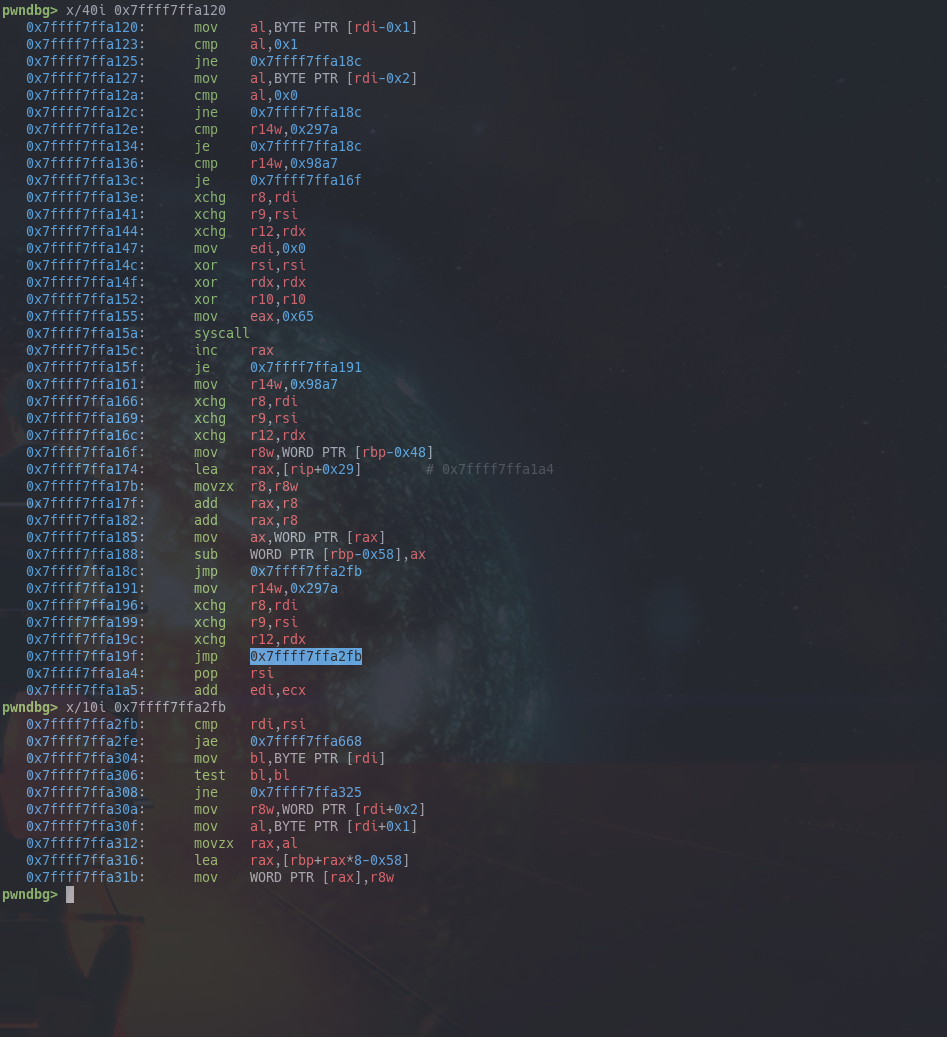
So what happens here?
- We check the last 2 bytes of the previous instruction to be 1 and 0. These are the registers involved in the subtract instruction.
- We check
r14wagainst0x297aand0x98a7. You can see if0x297amatches, then it jumps to the end and continues with executing the next instruction in the bytecode buffer. If0x98a7matches, we jump to some computation. - Otherwise, you see we setup arguments and request syscall
0x65, which isptrace. This is a common anti-debugging technique on x86_64 ELF binaries on linux, since the call will fail if a debugger is already attached. - If the call fails if will store
0x297aintor14w, otherwise we store0x98a7 - If the call is successful (no debugger), then you see we will load 2 bytes from
0x7ffff7ffa1a4at some index (this is the index of the current check we are doing), and we will subtract this value fromrbp-0x58, which is registerr0in the VM.
Stated in a more natrual language, if there's no debugger attached, we will subtract some hardcoded value from each node value check, before the jnz instruction in the VM, therefore the check values that we currently have are not the right ones.
Accounting for this extra subtraction we can fix our script as follows:
from pwn import *
toks = '3574;L;2223;L;1405;L;639;L;349;L;121;UR;117;UUR;251;L;118;UR;32;UUUR;668;L;312;L;101;UR;110;UUR;324;L;102;UR;111;UUUUR;710;L;277;L;201;L;101;UUR;32;UUR;317;L;104;UR;116;UUUUR;1312;L;632;L;257;L;115;UR;110;UUR;264;L;116;UR;116;UUUR;576;L;235;L;101;UR;102;UUR;233;L;97;UR;33'

k = b'\x5e\x01\xcf\x00\x4e\x00\xf1\xff\x7e\xff\xcc\xff\xde\xff\x57\x00\x05\x00\x45\x00\x60\x00\x1a\x00\x0f\x00\x01\x00\xfa\xff\x03\x00\xf8\xff\x8e\x00\x99\x00\x13\x00\x04\x00\x53\x00\xfa\xff\xf7\xff\x03\x00\x51\x00\x43\x00\x4e\x00\x00\x00\xff\xff\xff\xff\xb8\xff\xf5\xff\x0f\x00\x30\x00\x03\x00\xd9\xff\x1f\x00\xfe\xff\x5c\x00'
hiddens = [u16(k[x:x+2]) for x in range(0, len(k), 2)]

root = {}
toks = toks.split(';')
hptr = 0

for t in toks:
    try:
        root['val'] = int(t) + hiddens[hptr]
        hptr += 1
    except:
        for direction in t:
            if direction == 'U': root = root['parent']
            elif direction == 'L':
                if 'left' in root: root = root['left']
                else:
                    root['left'] = {'parent': root}
                    root = root['left']
            elif direction == 'R':
                if 'right' in root: root = root['right']
                else:
                    root['right'] = {'parent': root}
                    root = root['right']

while 'parent' in root:
    root = root['parent']

def compute_sums(root):
    root['sum'] = root['val']
    if 'left' in root:
        compute_sums(root['left'])
        root['sum'] -= root['left']['val']
    if 'right' in root:
        compute_sums(root['right'])
        root['sum'] -= root['right']['val']

def pot(cur):
    if 'left' in cur: pot(cur['left'])
    print(chr(cur['sum'] % (2**16)), end='')
    if 'right' in cur: pot(cur['right'])

compute_sums(root)
pot(root)
print('')
Notice, how we now have the hiddens array, which contains the extra values that are subtracted from the check value. We increase the node value by this extra amount, so that we can recover the correct user input.
Now when we run the correct script we get:
ECSC{re_tooling_is_so_awesome,right?,_,}
This is the flag, which is throwing shade at RE tooling for not recognizing/displaying this hidden section.
What actually happened
While setting a breakpoint in the discovered hidden/unmapped section did work and did get us the flag, one might still wonder how control flow reaches that point in the first place, or how this supposedly unmapped section shows up in the binary at all.
Luckily Redford, the author of the challenge gave an amazing talk on the final day, which among other topics also discussed how this challenge works.
Why did unmapped code show up
Recall, that the hidden assembly is not actually mapped according to the elf header.
The header is mapped from 0x00-0x120 in the file, and the next section is starting from 0x1f4.
The granularity of mmap allocating some memory is measured in pages (commonly 4KB sections of memory).
When the bytes from offset 0x1f4 in the file get mapped into 0x41f4 in memory, in fact the whole page containing 0x1f4 in the file gets mapped.
If we look at the mappings in GDB, we see something like this:
    0x7ffff7ffa000     0x7ffff7ffb000 r-xp     1000      0 tiny-crackme
    0x7ffff7ffe000     0x7ffff7fff000 r-xp     1000      0 tiny-crackme
The first one is the page for the ELF header from 0x00-0x120 in the file, yet in memory we see the entire page.
Similarly the second is the first code mapping from 0x1f4 in the file, but if you look at the start of this page:
+0000 0x7ffff7ffe000  7f 45 4c 46 02 01 01 00  00 00 00 00 00 00 00 00  |.ELF....|........|
+0010 0x7ffff7ffe010  03 00 3e 00 01 00 00 00  6e 46 00 00 00 00 00 00  |..>.....|nF......|
+0020 0x7ffff7ffe020  40 00 00 00 00 00 00 00  00 00 00 00 00 00 00 00  |@.......|........|
+0030 0x7ffff7ffe030  00 00 00 00 40 00 38 00  04 00 40 00 00 00 00 00  |....@.8.|..@.....|
yep, that is the ELF header from the start of the file.
This is pretty cool, as you now have 2 pages including some code that is supposedly not mapped into memory from the file (at least according to the ELF headers).
So in short, the hidden unmapped code got included in memory because it was on the same page as some other mapped code.
Why did we jump to the hidden location
This one is a bit more tricky and it's super cool!
The magic happens at the end of the first section at offset 000043d9 in memory.
The last instruction here is a jump, which will go to the logic fetching the next instruction after the subtraction operation is done.
The base of this section is at 0x41f4 and there is a discrepancy between the size we read from the file (0x1e7) and the size we map into memory (0x1ea) as seen from the ELF header.
According to ELF specification, when the mapped memory exceeds the amount of bytes read from the file, the extra bytes in memory should be zero-filled.
However, this part of memory is not writable (it's marked as read-execute) and instead of zero-filling the loader will actually copy the extra bytes (3 in this case) from the file!
So our JMP instruction which was e9 1d 00 00 00 in ghidra, suddenly will become e9 1d 07 00 00 when actually loaded into memory, we can confirm this using GDB.
That modification will change the offset of this 32-bit relative jump instruction, so that it will point to another jump instruction, which will jump exactly into the hidden region that was explained in the previous section.
A super interesting discrepancy between what the loader actually does and what RE tools (ranging from a simple objdump to large suites like ghidra and IDA) display to the user.
Summary
In short, this is a really cool challenge from Redford, which on the surface looks like yet another VM reverse challenge, but actually brings several cool ELF tricks to make the challenge unique and interesting.
A nice approach for the VM reverse, which I am quite happy with in the end, was the mixed use of dynamic and static analysis, and especially the balance between the two techniques. Note how dynamic analysis was really crucial in understanding the linked list, and later on the binary tree operations quite quickly, without having to analyse the operations in detail.